Reclaimer Primary Steelwork Upgrade — Execution Sequence Validation

Challenge
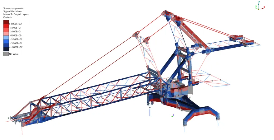
A major engineering contractor engaged Igneum to validate the execution methodology for primary steelwork upgrades on a large bucket wheel reclaimer at a Pilbara port facility. The upgrades — covering the boom, portal structure, and slew deck — had been designed in a prior phase with a critical assumption: that the existing structure would be in a near-zero stress state at the time of welding. Any residual stress present in the structure during welding would be directly additive to in-service stresses, potentially invalidating the original compliance calculations.
The challenge was that achieving this low-stress condition was not straightforward on a machine of this scale. The boom and portal carry significant self-weight loads, and the stress field at each upgrade location changes substantially depending on machine configuration — the amount of counterweight installed, whether the luff cylinders are under pressure, and where the boom is supported. Finding a sequence of operations that brought all upgrade locations below the target stress threshold, while maintaining structural integrity and stability at every intermediate step, required a rigorous analytical approach.
Approach
Igneum developed a validated execution sequence using multi-step non-linear finite element analysis, simulating each phase of the construction program as a continuation of the previous state.
Non-Linear Simulation Framework
The analysis used the Abaqus implicit solver with large-displacement theory throughout. Each construction step — counterweight removal, boom support tower addition, luff cylinder bleeding, and hydraulic jacking — was modelled by directly modifying the finite element model at the corresponding load step rather than treating loads as independent cases. This approach allowed the accumulated deformation and stress state from each prior step to carry forward into the next, giving a realistic representation of how the structure would actually behave through the sequence. The global model was refined at critical boom locations with high-fidelity shell elements to improve local accuracy.
Staged Counterweight Removal and Boom De-Stressing
Each boom upgrade location reaches its minimum stress state under a different machine configuration. A single counterweight removal step was insufficient — each removal stage shifted the mass balance of the machine and redistributed stress within the boom structure in a different way. Igneum evaluated numerous combinations of support locations, jacking points, and jacking forces to identify the lowest practical residual stress at each upgrade location.
The validated sequence removes counterweight in three stages, with temporary support towers placed at specific locations before the first removal and a mid-boom jacking arrangement introduced at a later stage. The luff cylinders are fully bled and locked off on low-pressure relief valves throughout, removing cylinder force as a variable. Each step was checked not only for residual stress but for machine stability and structural adequacy under the governing loads applicable at that phase, including out-of-operation wind.
Portal De-Stressing Through Jacking
The portal structure presented a distinct problem. The portal is not relieved by counterweight adjustments in the same way as the boom, and the initial stress field at the portal upgrade locations exceeded the target stress threshold. Igneum designed a four-point hydraulic jacking scheme — applied asymmetrically at the trouser legs and portal side legs — to introduce controlled deflection and relieve the portal stress field ahead of welding.
The jacking forces were selected and sequenced to bring all affected portal upgrade locations below the target stress threshold. Jack selection, expected stroke, and loading increments were specified to allow the contractor to confirm and control the jacking process on-site.
Stability and Buckling Through Every Step
Throughout the sequence, global machine stability was maintained and verified at each step. Member buckling was evaluated at all critical steps, including the jacked configuration, which represented the highest risk state for the compression chord elements. Reaction loads and working load limits were provided to the contractor to guide the structural design of the temporary support towers.
Outcomes
- A step-by-step validated execution sequence was produced covering all primary structural upgrade locations across the boom, portal, and slew deck, with specific counterweight quantities, jacking forces, support positions, and cylinder states defined for each phase
- Residual stress was brought below the target stress threshold at all critical weld locations, preserving the validity of the in-service compliance calculations
- Buckling resistance was confirmed at every governing construction step, including the most critical boom-jacked configuration, providing confidence that no intermediate state would compromise structural integrity
- Specific jacking equipment was selected and load increments defined to allow controlled, verifiable force application on-site, with clear hold points and acceptance criteria for the contractor
- Reaction loads, working load limits, and boom tower capacity requirements were provided to enable the contractor to design and verify temporary lifting and support equipment independently
- The validated sequence and supporting analysis gave the contractor a clear, auditable basis for proceeding into the execution phase — demonstrating to the asset owner that the low-stress conditions assumed in the original design would be achieved at every stage of the upgrade
Related services
Ready to discuss your next project?
Whether you need a full engineering assessment, specialist analysis, or an independent technical review — we're here to help. Get in touch to discuss how Igneum can support your operation.